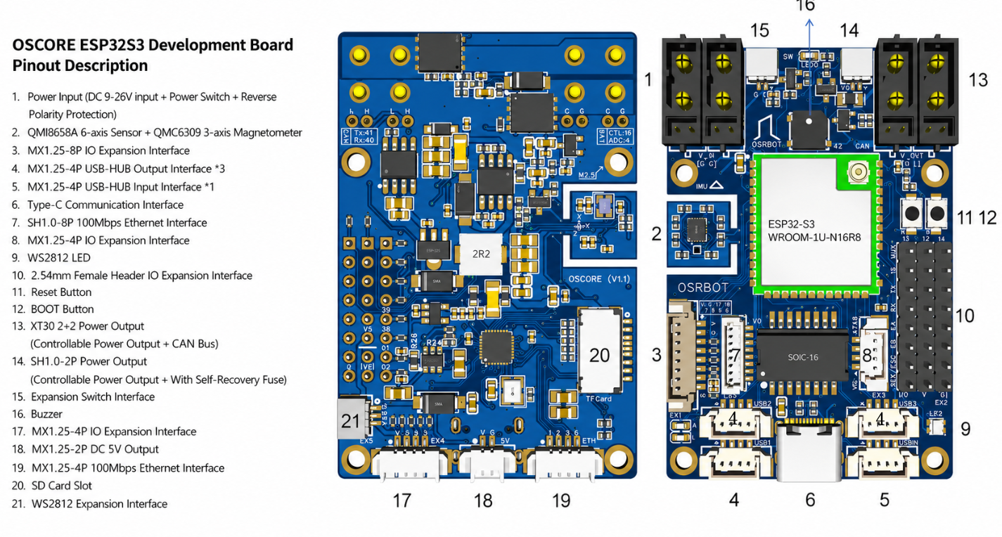
THE OSCORE BOARD.
OSCORE is the NeoRacer's power-distribution and control board, the one piece of custom electronics in the car. It is an ESP32-S3 robot controller that takes the LiPo in, fans out clean 5 V and 3.3 V rails, reads the onboard , and drives the motor and servo. It is the board the Jetson talks to over USB.
A ROBOT CONTROL BOARD.
OSCORE is built around the ESP32-S3-WROOM-1U module and pulls the pieces a small autonomous robot needs onto one board: a 6-axis IMU and a magnetometer, CAN bus, 100 Mbps Ethernet, a USB hub, an SBUS receiver input, outputs for the and servo, and an encoder input. The Jetson runs the autonomy; OSCORE is the real-time layer underneath it that actually moves the car and reads the sensors that need microsecond timing.
Power distribution
Motion + sensing
Comms to the Jetson
ESP32-S3, WROOM-1U.
| Parameter | Specification |
|---|---|
| Module | ESP32-S3-WROOM-1U-N16R8 |
| CPU | Xtensa LX7 dual-core @ 240 MHz |
| Flash | 16 MB (Quad SPI) |
| PSRAM | 8 MB (Octal SPI) |
| Wireless | Wi-Fi 4 (802.11 b/g/n) + BLE 5.0 |
| Antenna | U.FL (IPEX) external |
| Debug | USB OTG / Serial-JTAG, UART0 on RXD0/TXD0 |
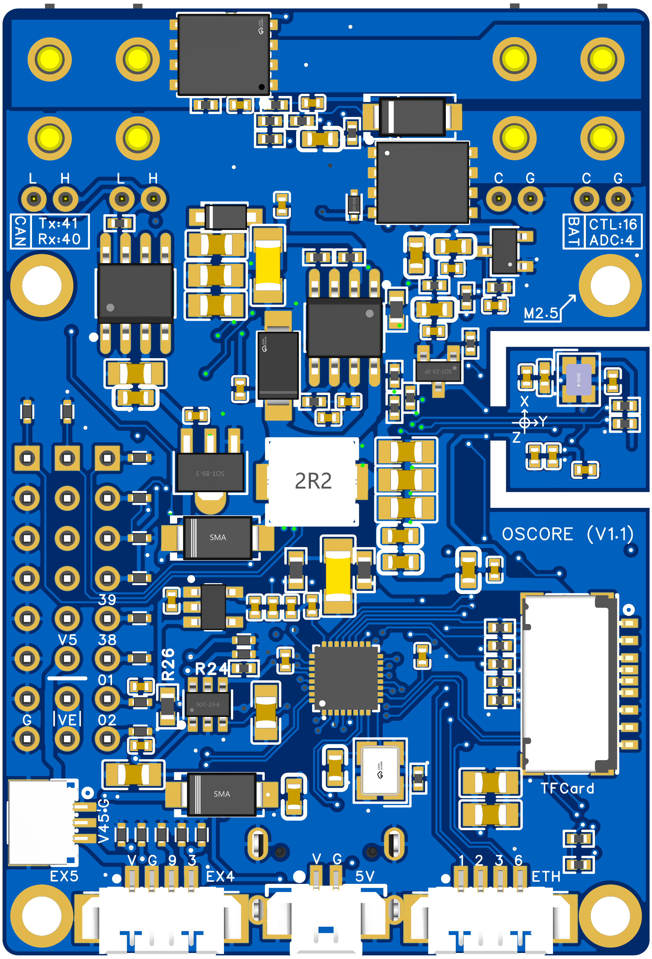
THE POWER SYSTEM.
A single 9 to 26 V input feeds a two-stage conversion: a TPS54540 switching regulator makes the 5 V rail, an AMS1117 LDO makes 3.3 V, and the raw input passes through to the ESC. The input has reverse polarity protection.
| Rail | Source | Voltage / current | Usage |
|---|---|---|---|
| VCC_IN | XT30 / Type-C | 9 to 26 V | Main input, reverse-polarity protected |
| VCC_5V_IO | TPS54540 DC-DC | 5 V / 5 A | IO peripheral power |
| VCC_5V | VCC_5V_IO + MOSFET | 5 V (switched) | USB hub, CAN, WS2812 |
| VCC_3V3 | AMS1117-3.3 LDO | 3.3 V / 1 A | ESP32-S3, IMU, buzzer |
| VCC_ESC | VCC_IN (passthrough) | 9 to 26 V | ESC power output |
THE ONBOARD IMU.
The IMU lives on this board, two parts on a shared I2C bus. A QMI8658A gives the 6-axis accelerometer and gyroscope; a QMC6309 adds the 3-axis magnetometer, so together they support a 9-axis heading. The ESP32-S3 reads them and publishes on /imu once the driver is up.
| Sensor | Type | I2C | Range |
|---|---|---|---|
| QMI8658A | 6-axis gyro + accelerometer | 0x6B | gyro ±16 to 2048 dps, accel ±2 to 16 g |
| QMC6309 | 3-axis magnetometer | 0x7C | ±30 Gauss |
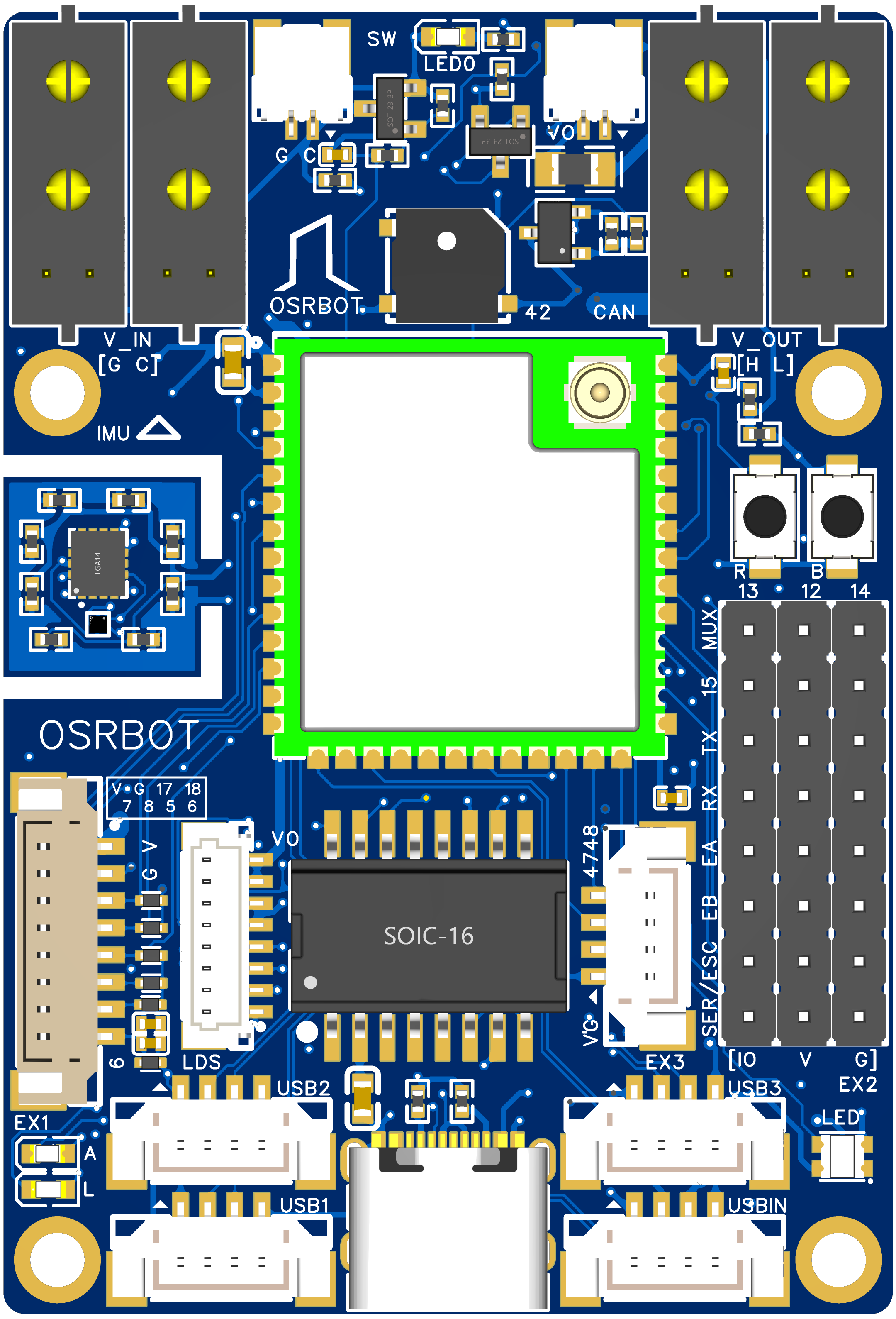
INTERFACES AND CONNECTORS.
| Interface | Type | Function | Part |
|---|---|---|---|
| DC power input | XT30 (2+2) | Main supply, 9 to 26 V | TPS54540 |
| USB Type-C | Type-C 16P | Flashing, USB comm, 5 V | CH339F hub |
| USB hub | 4x USB-A | Cameras, drives, dongles | CH339F |
| Ethernet | RJ45 100M | 100 Mbps comms | HR641680E |
| MicroSD | TF slot | External storage | via CH339F SDIO |
| CAN bus | Header / terminal | CAN 2.0, up to 1 Mbps | TJA1050T |
| SBUS / PWM / encoder | Pin header | RC in, ESC + servo PWM, encoder A/B | VCC_5V_IO |
| WS2812 LED | 3P header / onboard | Programmable RGB | IO46 |
| Buzzer | Onboard | Active buzzer | IO42 |
| Reset / Boot | Touch buttons | Reset + flashing mode | BOOT + RESET |
| IO expansion | 2.54 mm header | Spare ESP32-S3 GPIO | SPI / I2C / UART |
| Power output | XT30 (2+2) | VCC_5V / GND out | External |
ELECTRICAL LIMITS.
THE SOURCE FILES.
OSCORE is open hardware. The complete electrical documentation is yours to read, the same files the board was built from:
- Hardware manual (PDF) · the full functional reference, every module and pin.
- Schematic (PDF) · the complete circuit.
- Reference designator map (PDF) · every component located on the board.