Skip to main content
Home
NeoRacer
Documentation
Community Dev
Support Us ▾
About ▾
Home
NeoRacer
Documentation
Community Dev
Support Us ▾
About ▾
Menu
NEORACER
DOCS
NEORACER
DOCS
Search…
⌘K
Home
Setup
▸
Unbox
Charge & power
Prepare the car
Install the driver
Connect to the router
Test the system
Hardware
▸
Overview
Compute
Sensors
▸
LiDAR
Camera
IMU
Encoder
Remote control
Dot matrix
Drivetrain
OSCORE board
Chassis & CAD
Software
▸
API Reference
▸
Reference
▸
Legal
▸
These docs are public and open source.
Edit on GitHub
Hardware
›
Overview
0
1
THE NEORACER
HARDWARE
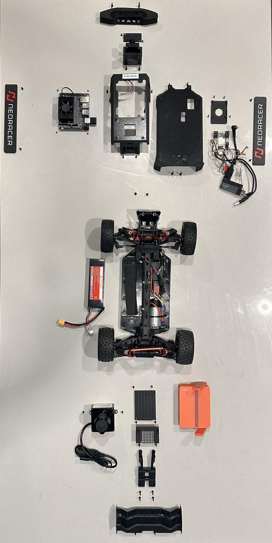
FIG. A / THE PARTS OF THE NEORACER
01
Front bumper
02
Camera
03
Jetson Orin Nano
04
Sidepod
05
OSCORE PCB
06
Steering servo
07
LiPo compartment
08
ESC
09
1:12 chassis
10
Motor
11
LiDAR
12
Dot matrix display
13
Cudy router
14
Rear wing
Click a label to open that part's page.
FIG. B / NEORACER SYSTEM DIAGRAM
Camera
LiDAR
LED matrix
Router
RC receiver
Encoder
Jetson
Orin Nano
Power module
Lithium battery
Power switch
OSCORE controller
USB hub
ESP32-S3
WROOM-1U N16R8
DC 9-26 V
DC motor
ESC
Servo
USB-A 5P
USB-C 4P
MX1.25 4P
RJ45 + USB-C
SH1.0 3P
MX1.25 4P
USB-A 4P
DC5525
XT60
XT30
2P
2.54 3P
2.54 3P
The signal and power map of the car. Click a component to see how it connects.
◀
Previous
Test the system
Next
▶
Compute