ReassemblyNEORACER DOCS
NEORACER DOCS
These docs are public and open source.Edit on GitHub
BUILD / REASSEMBLY

THE REASSEMBLY.

Taking the car apart is half the fun of a modular platform, and this page is the way back. It walks the NeoRacer from a pile of parts to a rolling car, one step at a time, with a photo at every stage so you always know what done looks like. The component tour is the companion page if you want to know what each part does before you bolt it back on.

In progressPhoto per stepFull guide in progress
THE STEPS

THE SEQUENCE.

The build runs nose to tail: chassis, front end, camera, the printed mid section with its electronics, the top plate with the sensors, the screws that tie the layers down, and the covers to close it up.
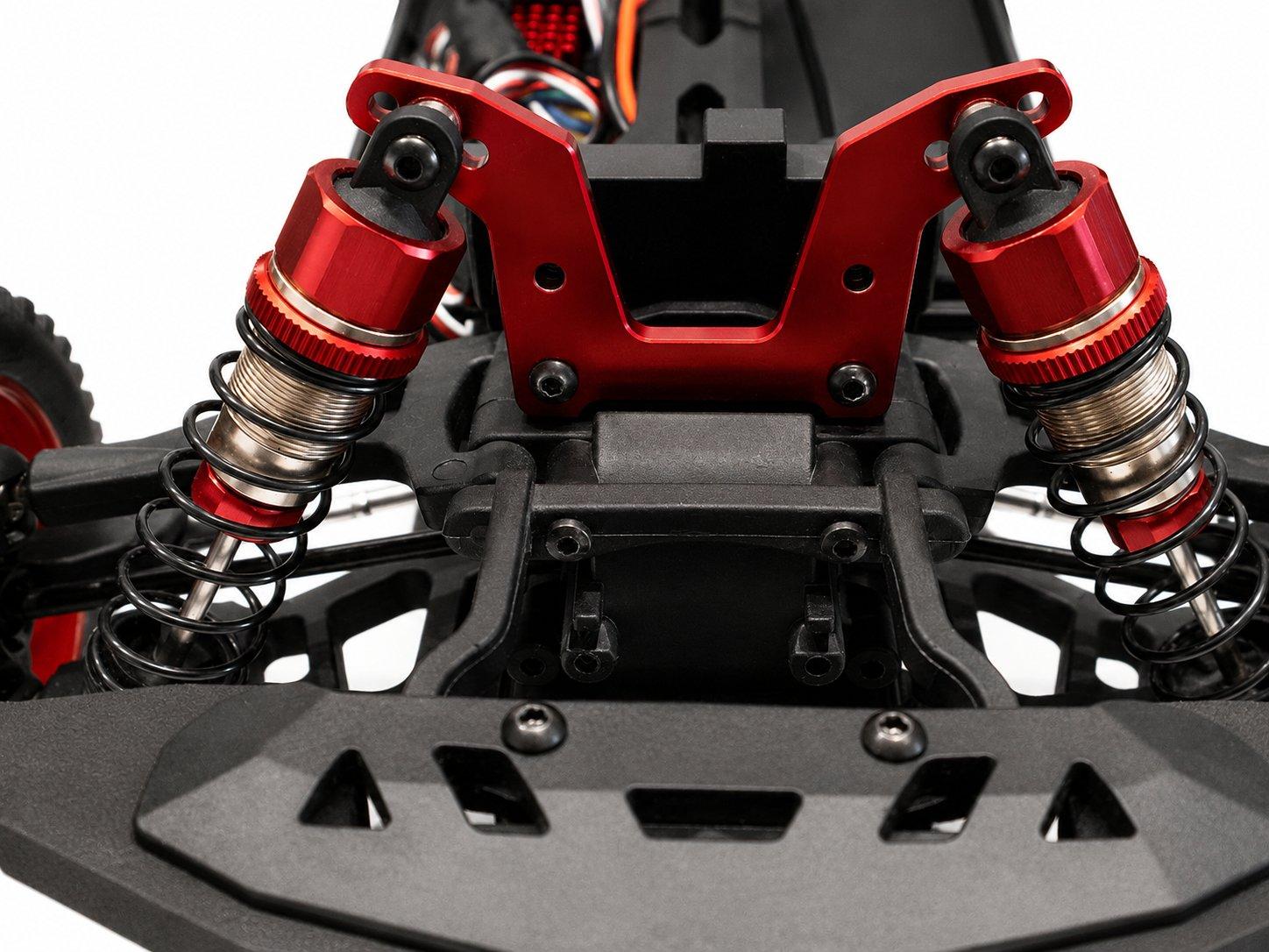
The bare rolling chassis with its rear shock tower and oil-filled shocks01

The chassis

Reassembly starts where the component tour starts, with the rolling chassis. Set it on a clear table with the rear shock tower facing you. Everything from here bolts onto this frame.

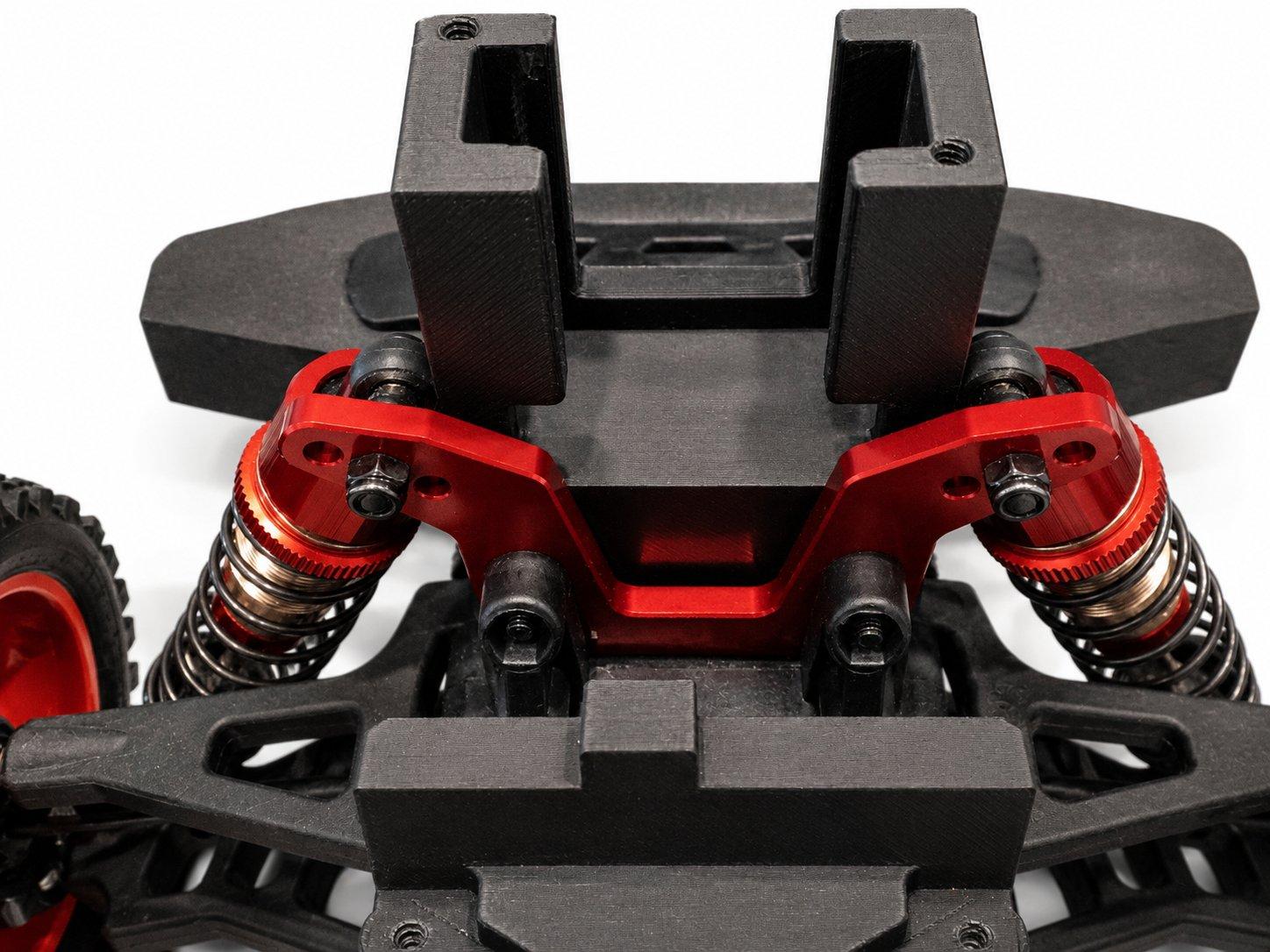
The front bumper and printed upper bracket seated over the red front shock tower02

The front end

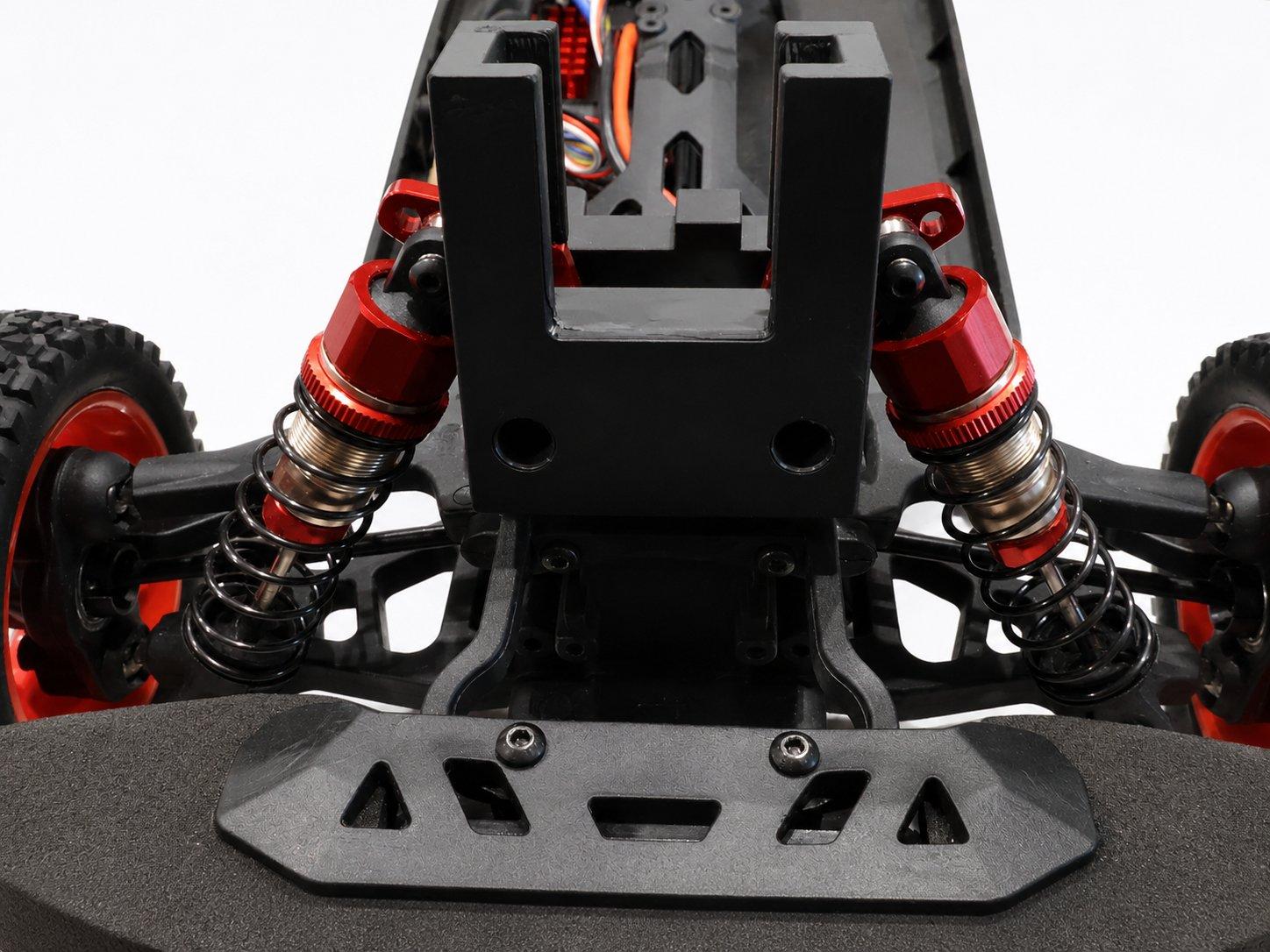
The front bumper and the printed upper bracket come together at the front shock tower. Seat the bracket over the tower, start every screw, and then tighten them down evenly.

The empty camera bracket on the front end, open side facing forward03

The camera mount

With the front end together, the camera bracket goes on top with its open side facing forward, ready to take the camera box.

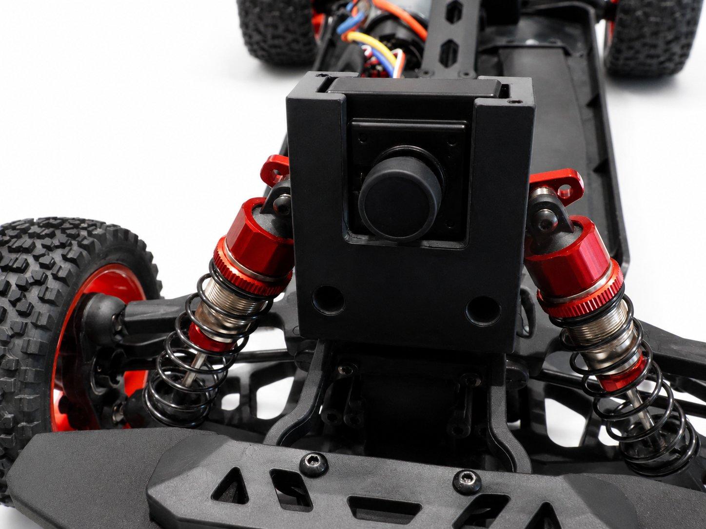
The camera box mounted in its bracket with the lens facing forward04

The camera

The camera box drops into the bracket, lens forward. Leave its cable free for now; it connects once the top layer goes on.

Camera
The printed mid section with its orange battery lid held above the chassis05

The mid section

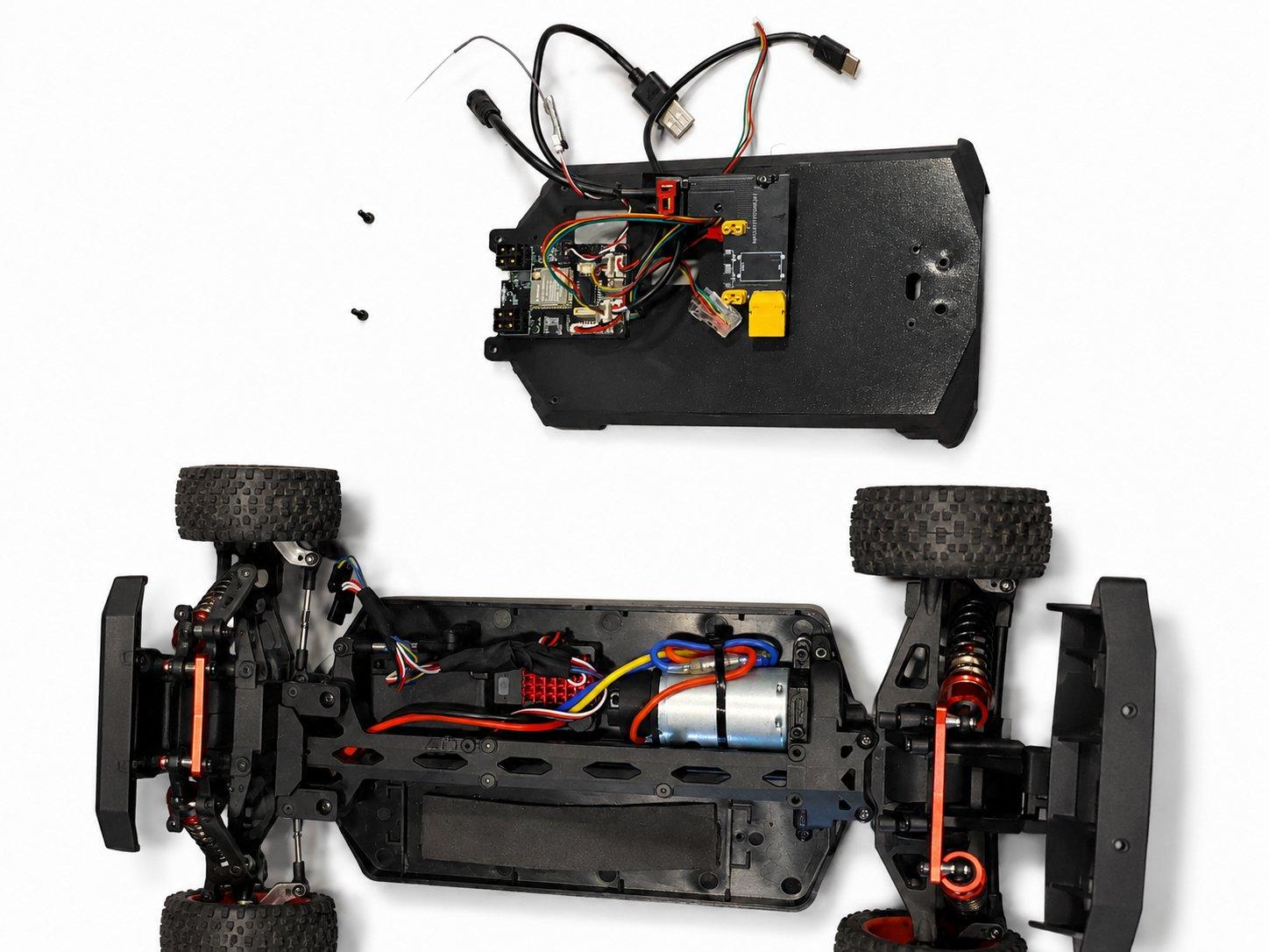
The printed mid section, with its orange battery lid, lowers onto the chassis as one piece and screws down to the chassis plate.

The OSCORE board's harness routed along the underside of the mid section06

The board wiring

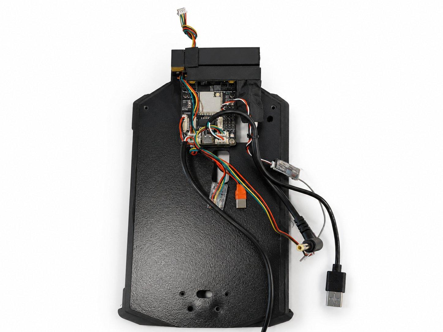
The OSCORE board's harness routes along the underside of the mid section, with the USB leads left out to meet the Jetson.

OSCORE board
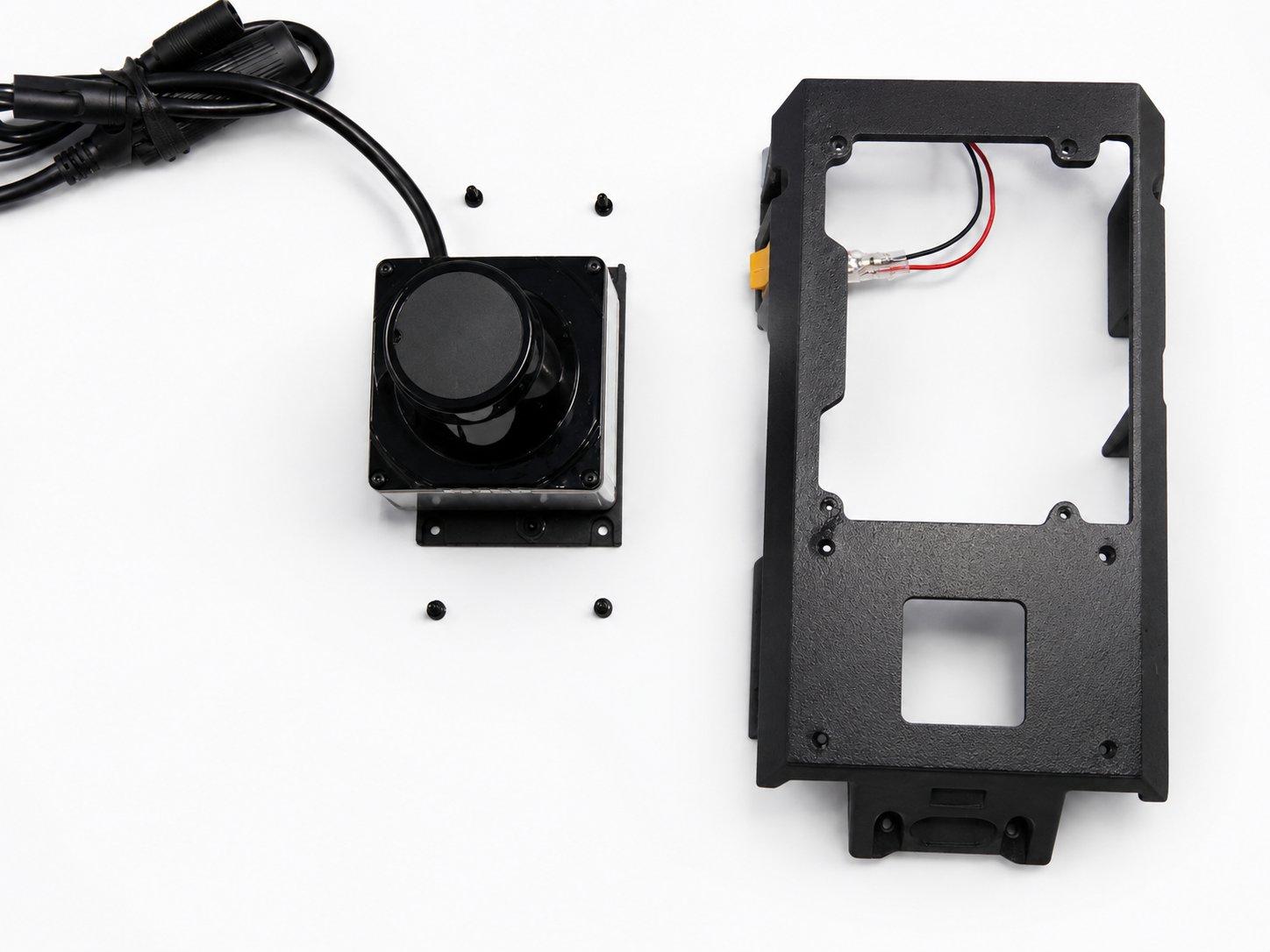
The LiDAR unit and its four screws beside the printed top plate07

The LiDAR

The top layer starts with the LiDAR. Four screws fasten it onto the printed top plate, scanner up.

LiDAR
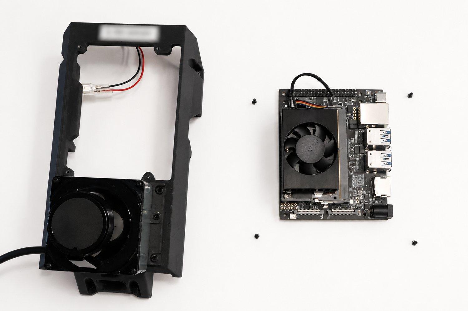
The top plate with the LiDAR set, beside the Jetson Orin Nano and its four screws08

The Jetson

With the LiDAR set in the plate, the Jetson Orin Nano lines up beside it with its four screws.

Compute
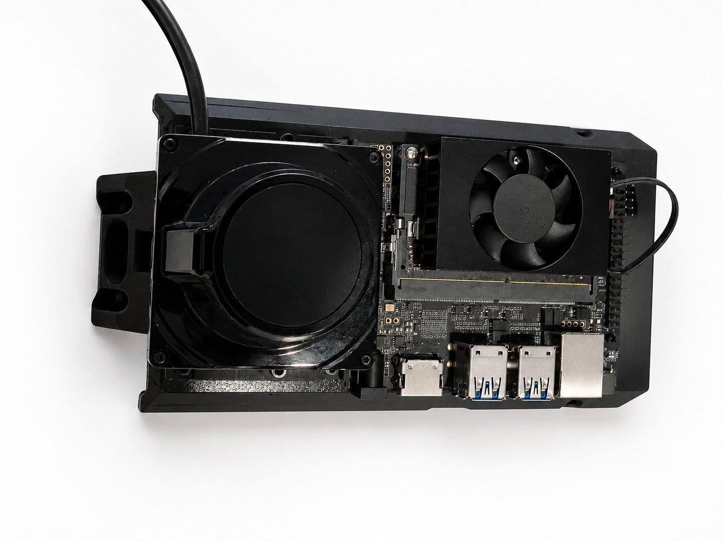
The loaded top plate with the LiDAR in place and the Jetson Orin Nano mounted beside it09

The top plate

The Jetson screws down, fan up, ports facing the rear, and the loaded top plate goes onto the car.

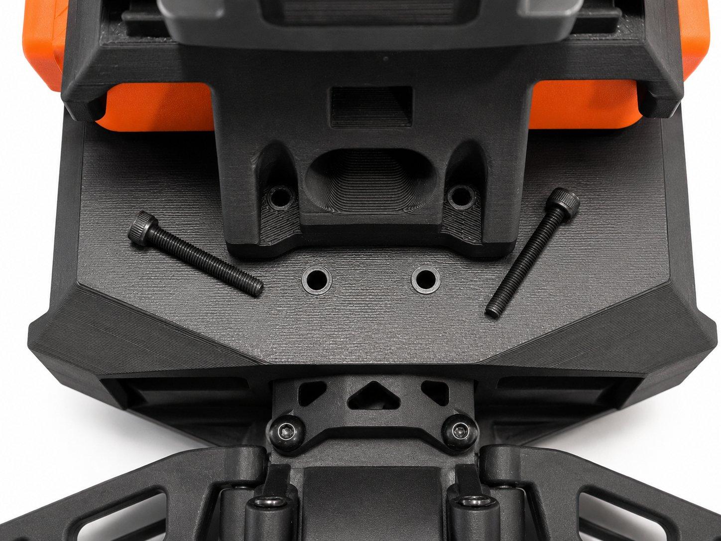
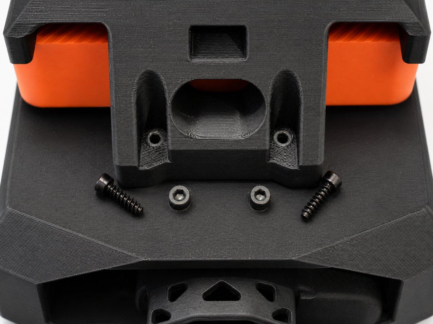
The two long screws on the rear deck that fasten the lower printed section to the chassis10

The chassis screws

At the tail, the two long screws run through the lower printed section and into the chassis, tying the printed body to the frame.

The two screws and washers that fasten the top layer to the lower printed section11

The layer screws

The next two screws, with their washers, attach the top layer to the lower printed section.

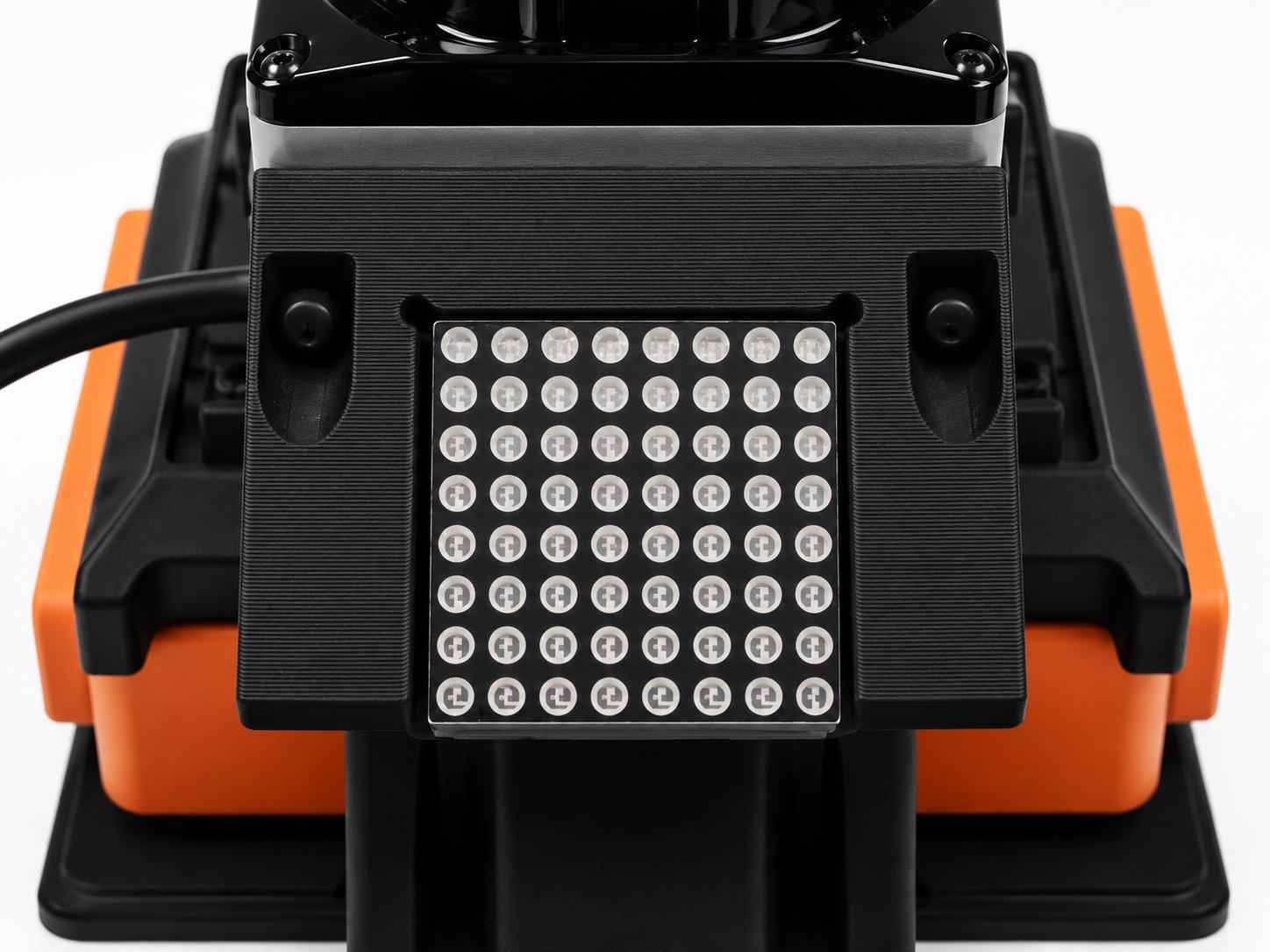
The 8 by 8 dot matrix mounted at the tail of the top stack, facing backwards12

The dot matrix

The dot matrix mounts at the tail of the top stack, facing backwards, so the car keeps its face.

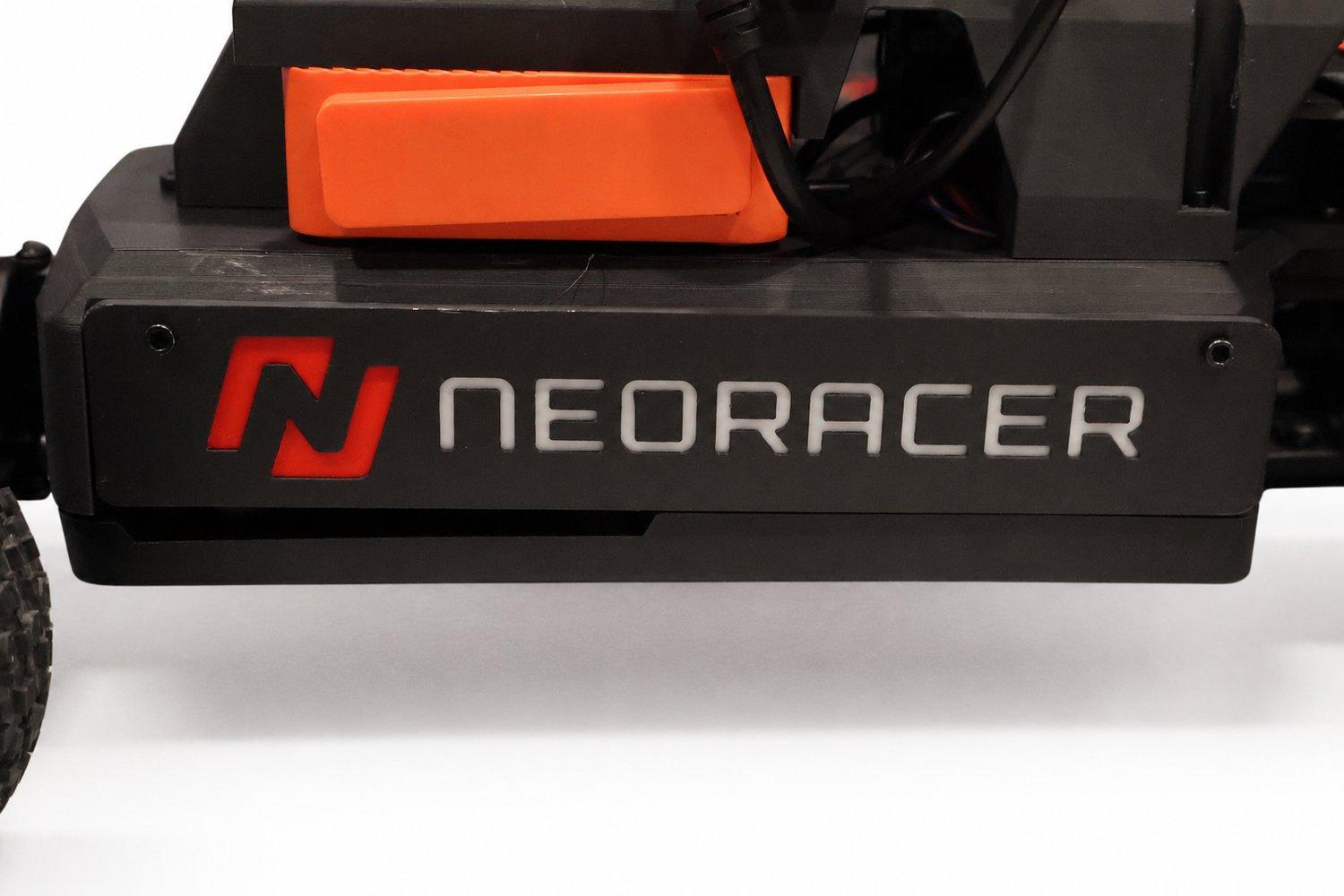
The NeoRacer side cover mounted on the finished car13

The side covers

The side covers close the electronics bay and put the name back on the car.

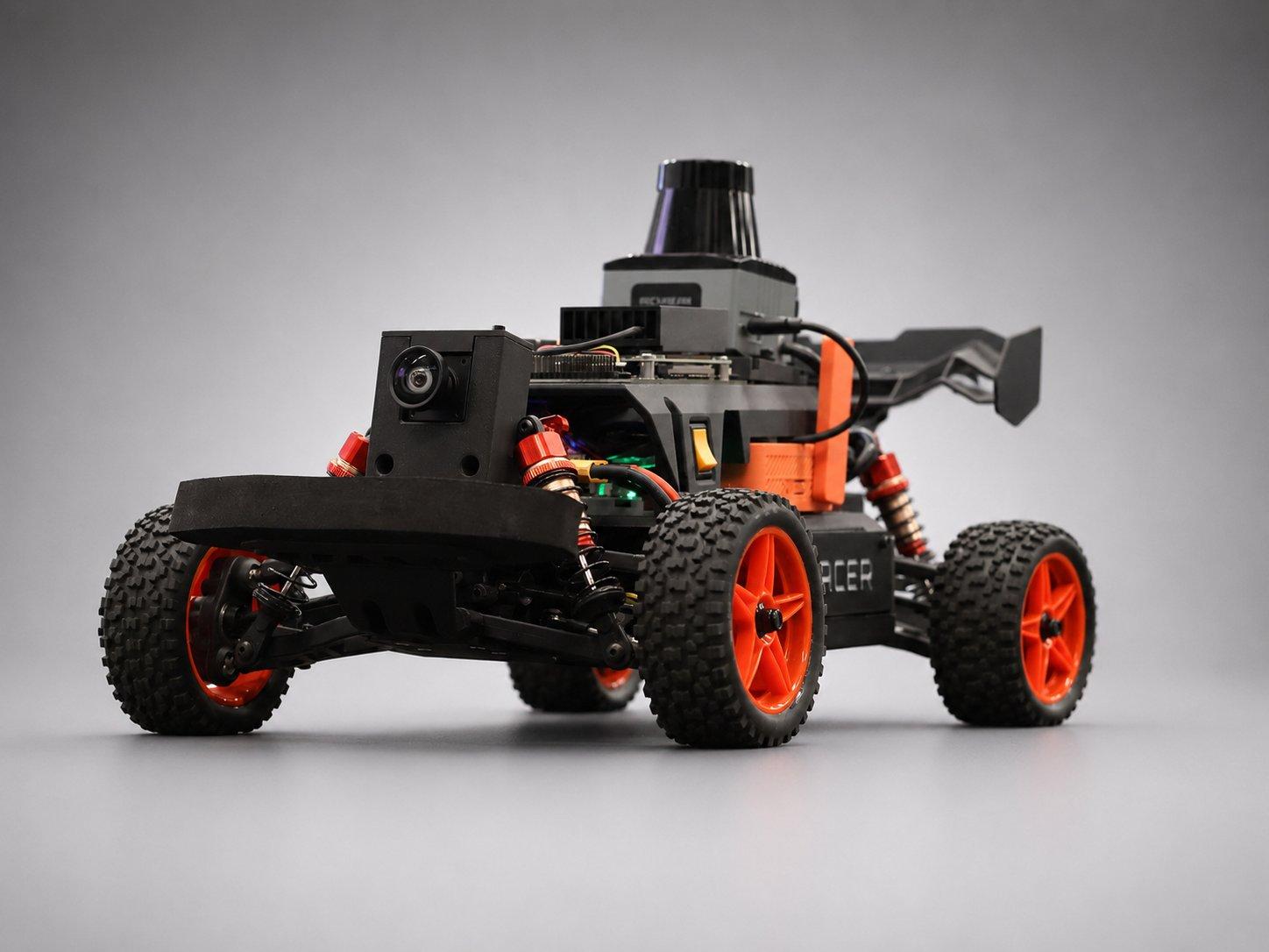
The fully reassembled NeoRacer, low studio angle, with the camera, LiDAR, and rear wing all mounted14

Back in one piece

That's the build. Camera up front, LiDAR on top, wing on the tail, and a car that is ready to drive the moment a charged battery goes in.

Charge & power